After getting my restored Union Switch & Signal H2 searchlight all set in the back yard, the next issue was a matter of controlling it. Sure, it would be easy enough to wire it for one aspect, or put in a toggle switch, or go with an off-the-shelf traffic signal controller, like many signal collectors do, that would just cycle through the aspects. But I’m me, and anything worth doing is worth massively overdoing.
I wanted to be able to control the signal via WiFi, and then be able to set the aspects programmatically. That way, I could change it using my phone or any other browser, or ideally eventually sync it with data coming out of ATCS Monitor using some python scripts. Since there wasn’t anything on the market that would do that, off to do some design work…
The Control Board
The board really had three major design goals:
- Drive both the signal lamp (~12V @ 2A, incandescent bulb through a resistor in the head) and the relay coil (>5.5V @ 25-30mA). This would be a simple on/off drive for the light bulb, but the relay requires a bipolar drive to get all three aspects.
- Allow me to control the signal aspect (including off) over WiFi and IP-based networking, using a built-in webserver to allow me to change the signal from anything with a browser, or alternately with some scripting logic.
- Stop surges that might come down the control wires from that 11 foot aluminum lightning rod I just put up in the yard, sacrificing itself if it must in order to not inject dangerous surges into the house wiring.
First Priority: Lightning Protection
Colorado has plenty of lightning, particularly in our typical summer afternoon thunderstorms. Ask any signal maintainer and they’ll tell you lightning can really screw things up in a hurry. I remember one summer night when a particularly charged storm passed through the Utah desert. That was back when much of the former D&RGW out there was still using open wire line between signals. Listening to the scanner, the DS told Amtrak that signals were down most of the way from Green River to Helper on account of multiple lightning hits, and they were going to spend a lot of time running at restricted speed and getting talked by all sorts of signals displaying stop or nothing at all.
In that case, the damage was to a bunch of company equipment inside the company’s metal sheds, but at the end of the day it just amounted to a bunch of equipment change-outs and quite a bit of unexpected overtime for the maintainers. In my case, a lightning strike might blow out a bunch of my things in my house, and possibly set the place on fire. That’s far worse. Safety has to be first on the list here.
Grounding
Note: I am not a grounding expert. There’s a whole science to it and a whole field of experts devoted to knowing all the little details. I think I’ve got this right. If you happen to be actually be a grounding expert, I’d appreciate any feedback.
The signal mast itself has a ground rod, but that in and of itself isn’t enough since this will be connected to mains power. Grounding rods usually have a few ohms of resistance in their contact to the actual “ground”. The National Electric Code in the US allows for up to 25 ohms in a residential install, whereas 1-5 ohms is typical for commercial installs or critical facilities like substations. At typically low (ideally zero) ground currents, that doesn’t matter. If you suddenly introduce a large current through one of those rods (such as grounding a strike at the signal), you now have several hundred or thousand volts of potential between the two because of Ohm’s law. Simply putting a rod at the signal isn’t adequate if you have a significant lightning event. You need a good bonding wire between the grounding points to make sure the potential everywhere rises and falls together, and you don’t suddenly see a couple thousand volts between your signal control lines and your house power.
So, in my case, I installed a #6 copper bonding wire between the signal and its ground rod, the satellite dish and pole, and the house grounding point at the meter. That should keep everything at the near same potential.
Control Board Surge Protection
Now that we’ve got a good solid system ground in which to dissipate any energy that would happen to hit the signal mast, let’s look at the protection built into the control lines to dissipate any direct or inductively-coupled surges in the coil and lamp control lines. I’ve built three layers of protection into the control board itself.
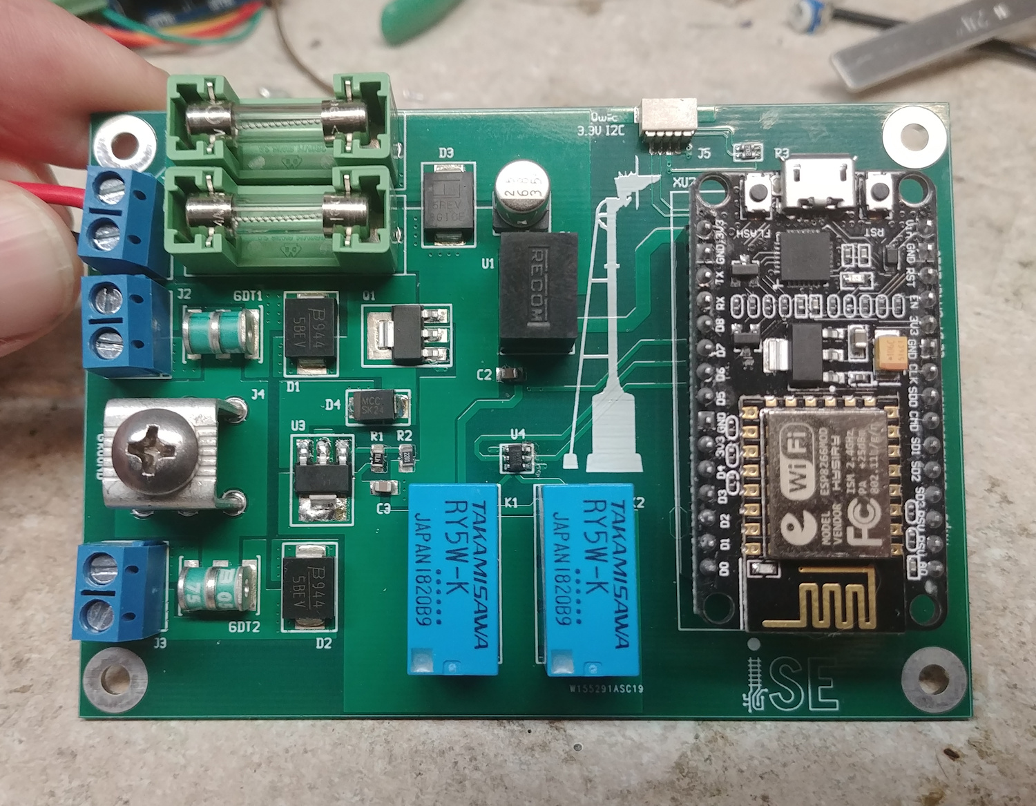
First are a set of TVS (transient voltage surge) suppression diodes located near where the lines from the signal come into the board. (D1 & D2) These things are rated for a couple hundred amps, and will clamp at 18V between any of the control wires within nanoseconds of a surge. These are intended to clamp small surges caused by induction before they can exceed the voltage rating of any of the electronics and cause damage.
The second is a set of gas discharge tubes located on the signal wires. (The green things near the terminal blocks – GDT1 & GDT2.) Each is essentially a precision spark gap that, at 75V or greater from any signal wire to earth ground, will arc over and shunt the energy to the earth ground. These things are remarkably robust, rated for 10,000 amps for a few tens of microseconds. That’s why that giant lug is on the board – to provide a very low impedance path to earth ground. They’re much slower to act than the TVS diodes, but these are there to handle the much heavier hits, such as a mild strike that somehow coupled into the cables.
The third feature is fuses on both of the power supply leads. These are partially there to protect the board and power supply in the case of a shorted output, but they’re also there to protect against a very large hit propagating back through the power supply to the house mains. Fuses, however, are painfully slow compared with the first two lines of defense – on the order of 50-100mS to break even under high current.
Driving the Load
Now that we’ve gotten safety out of the way, we need to make the board actually do what it’s supposed to do – control the signal. The signal relay that forms the operating guts of an H2 searchlight fundamentally requires two elements to operate it – lamp power and coil power. Lamp power does exactly what you’d think – powers the bulb that makes the light. That goes to terminals E & F in the diagram below. Coil power drives a set of coils that pull colored discs (called roundels) into the light path to change the signal color. That goes to L- and M+.
The lamp control lines need about 10-12V at ~2A steady state, with the usual incandescent surge currents when the bulb first turns on. On this board, it’s driven straight off the 12V input, since the US&S lamp assembly in the head already has a ballast resistor on it. Mine is set to operate the lamp at ~10V (the usual rated voltage for railroad signal lamps) when 12V is applied. I decided against a relay, since I wanted flashing aspects, and I felt that solid state would be more reliable in the long run that a relay interrupting 2A currents ~40 times/minute. Instead, I went with a self-protecting low side driver – the ON Semi NCV8405 rated for 42V at 6A. These are essentially N-channel MOSFETs with a bunch of protection built in against excessive gate-source voltage, excessive current, and thermal failure. Plus, it would operate based on a 3.3V control signal directly from the ESP8266 microcontroller (more on that later).
The H2 relay coil needs a bipolar driver. If no power is applied, the internal arm rests in the middle and places the red roundel in the light path (position M in the above diagram). This is a railroad signal, after all, and fail-safe behavior is key. If the coil loses connections for some reason, you want the trains to stop. If power to the coil is applied in one polarity, it pulls the arm to the right and places the green roundel in the light path. If power is applied in the opposite polarity, it pulls the arm to the left and you get yellow/amber instead. My particular coil, the last time it was serviced in the 1990s, has a pick up voltage (the point at which it’s guaranteed to move) of 5.2V. At that voltage, it draws ~20mA or so. I decided to go for about a 7V drive. That seemed a reasonable compromise between minimizing power usage (and thus heat) and reliable operation. That 7V is provided by an on-board regulator, and then that is converted to a bipolar output using a pair of relays.
Connecting it to the Network
As I said at the beginning, the point of all this overkill was to link the signal to my WiFi network such that I could control the signal with a web browser or scripts. I took the super easy way out on this one. About seven years ago, the ESP8266 appeared on the market and almost immediately drew the attention of hardware hackers everywhere. It was a nearly all-in-one microcontroller with a built-in 802.11 b/g/n radio. All you needed was to add flash memory, a crystal, some passives, and a PCB antenna and you were off to the races developing a WiFi node. A number of companies from China rapidly turned these into small modules that took care of integrating all the essential hardware, and software developers managed to abstract all the hard software stack stuff and make them programmable from the Arduino environment.
Arduino? You’re supposed to be some sort of professional!
Yeah, I’m also professional enough to understand the difference between project and product. And doing all the gruntwork to bring up a WiFi layer, a network stack, and so on by myself sounds like way more work than the project justified. So I’m using a tested and proven stack under the small amount of application code I need to write. Plus it makes it far easier for others to modify to their needs.
In this case, I chose to use one of the ubiquitous NodeMCU boards. They’re essentially an ESP8266 with all its needs, a serial-USB converter, and a small voltage regulator on a module that plugs in using standard 0.1″ headers. That makes them incredibly easy to program – you install the ESP8266 toolchain in the Arduino environment, compile the code, and hit “Download” and it does. The added bonus is they’re easy to obtain for $5 or so.
If you do decide to build your own, be sure to change these three lines in the sketch before downloading it into the board:
const char* ssid = "YOUR-WIRELESS-NETWORK";
const char* password = "YOUR-WIRELESS-PASSWORD";
const char* nodeName = "backyard-h2";
nodeName (backyard-h2 in this case) is the name it will register with DNS, if you have local dynamic DNS set up. Set this to something meaningful for you.
ssid and password are your WiFi network name and password. No, I’m not dumb enough to check mine into public version control.
The Power Supply
The power supply was the easy part. I needed 12V at 3A or more, driven from 120 VAC. It would be a plus if it were relatively immune to dirt and moisture, since it would be installed in a (sealed) outdoor box.
Modern LED lightning has made a wide variety of high efficiency off-line switching converters available at very affordable prices. I went with the Mean Well LPV-60-12, which is a 12V 5A isolated converter with IP67 sealing (meaning it’s dustproof and waterproof for intermittent submersion). I picked mine up off Amazon for <$20. More than enough capacity for the ~2A that the signal lamp requires to operate.
Installation
In my case, I already had a weatherproof electrical box mounted on the satellite pole in the back yard. This seemed an ideal place to put the control logic, since it was far from the house (in case it actually had to take one for the team in a real lightning strike), waterproof, and had a conduit running back to the house that could deliver power. Plus it was only ~20 feet from the signal, so digging the shallow trench for the ground wire and the control cable (direct-bury 5 conductor sprinkler control wire) was easy work one afternoon.
Inside the box (installed years ago – a Bud NBB-15245), I mounted a piece of fire-retardant plastic sheet, cut to size, and then drilled holes to hold both the control board and the power supply. A few standoffs and M3 bolts later and everything was mounted up. Then it was a matter of pulling a ground wire and the signal cable through one of the cable glands installed on the bottom of the box. The 12ga ground wire connected the grounding lug on the board to the main ground wire on the pole, and the control cable was stripped and attached to the terminal blocks appropriately.


Controlling the Signal
So, you’ve got the board all hooked up and it’s on your network. Now what?
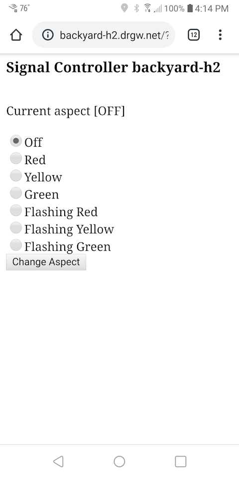
That’s pretty easy. If you just open a browser and enter a URL of http://x.x.x.x (where x.x.x.x is the IPv4 address of the signal on your local network, or in my case backyard-h2.drgw.net, since I have local subnet name resolution set up), you should get a page showing you a radio button list of aspect options or “off”. Pick one, hit “Change Aspect” and it should do just that. Yes, it’s some seriously ugly old school HTML, but it was good enough for what I needed.
Additionally, if you want to control it programmatically, there’s a hidden control URL that may eventually provide more options:
http://x.x.x.x/setAspect?aspect=Y
Y should be one of: red, yellow, green, flred, flyellow, flgreen, or off
A note on security: Other than securing the WiFi signal via WPA2, there isn’t any. There’s no authentication at all, and https isn’t an option. This is intended for secured private networks only, not on the public internet where miscreants could take control. Even then, since you’re obviously not going to use this in any safety-related application, the worst they could do is turn your reliable, slow-changing aspects into a rainbow disco projector.
The Controller In Action
Resources
The design is open hardware and all of the details are in the Iowa Scaled Engineering Github account, under the esp-searchlight project: