A couple weeks back at Spring Creek Model Trains’ show in Deshler, NE, someone asked about the Atlas All-Scales Signal System vs. the open standard Modular Signal System. (From here on out, we’ll refer to the Modular Signal System as MSS, but out of kindness to Atlas, a company I greatly like and appreciate for all they’ve done for our hobby, I’ll avoid abbreviating their signal system…) Basically they were looking for a simple working ABS signal system, and were wondering about my thoughts on each and if there was some way they might be made compatible.
Honestly I knew of the Atlas system, but I’d never spent much time looking into the details of it. I was surprised, however, that nobody had really jumped in to figure out how the modules communicated and published it. So, I picked up a few modules from eBay and went to work.
Comparing Atlas with MSS
The systems are actually rather similar. Fundamentally, both are designed to make signaling easy by simulating basic ABS signaling that “just works”, using easy-to-connect modular wiring between blocks and a simple logic scheme. There’s nothing complicated in either system about how the modules communicate, or how they’re configured.
There are differences, however. The most striking is that the Atlas system only supports a single direction of signaling on a given wire and set of boards. If you want bi-directional signaling, you need to run two signal buses – one for each direction – and need to have two sets of signal boards at each block boundary. MSS sends both directions over the same cable and most MSS signal nodes support bi-directional signaling.
Another key difference is that MSS also prescribes a clever detection scheme, using both optical and current detectors so that users need not equip all their cars with resistor wheelsets. Atlas recommends just using straight current detection, but doesn’t provide detectors themselves.
The Universal Signal Control Board
The foundation of the Atlas system is the Universal Signal Control Board. The USCB represents a block and its entry signal (going one direction). It’s essentially half of what those in the MSS world would call a “cascade node”, which sits at the boundary between blocks and has entry signals and detection for both. Each block would have one of these for each direction being signaled, and it would control the entrance signal in that direction and connect up to the block detector.
The USCB has the usual sorts of features you’d expect – being able to use common anode (positive) or common cathode (negative) LED signals, configurable for approach lighting, and able to either 2 block (red / yellow / green) or 3 block (red / yellow / flashing yellow / green) ABS system. There’s an open collector detector input (meaning you pull it to ground to say “I’m detecting!” and let it float otherwise, and a detector output that can be used to drive a panel or fascia LED. It also has outputs for driving some of the additional lamps found on position light signals (specifically the home/pilot light and the lunar aspect). Being a western modeler and a GCOR guy, I have zero idea what these mean under NORAC rules.
The boards also have a unique feature I haven’t seen elsewhere – the ability to force a signal indication. There are inputs for forcing red, yellow, flashing yellow, and flashing green, as well as one to force approach lighting. There’s one unfortunate bug with it, however. While forcing yellow trickles down to the previous block like you’d expect, triggering a flashing yellow, red does not work similarly. If you force a red, the previous signal will remain green. The Rin line tugs on the “Force Red” input that comes in on pin 4, and it looks like the microcontroller then doesn’t turn around and signal that back out on the pin 3 “red signal / block is occupied” line.
(Other note – the microcontroller – a PIC16F631 – only seems to read the CA/CC selection on power-up. This one took me a while to figure out when I couldn’t get my signals to respond correctly.)
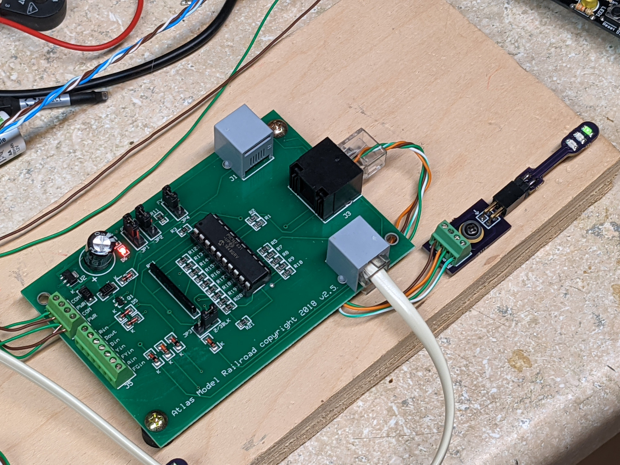
The signal driver lines already have resistors on them, and come out on an RJ45 (8p8c) connector known as J3. If you’re using Atlas’ signals, it’s quite handy – there’s a signal attachment cable that plugs right in. If you’re not using Atlas signals (such as my test setup below), you either need to use their DIY signal attachment cable or (as I did), crimp your control lines into an RJ45. Fortunately the pinout here is well described in the manual.
Here’s one on my bench hooked up to one of my temporary signals, just so I could play and poke around with it.
To get a better idea of how to use the USCB to set up signals, I recommend both:
– The Atlas All Scale Signal System Basic Operation Manual
– The Atlas Advanced Signal Guide
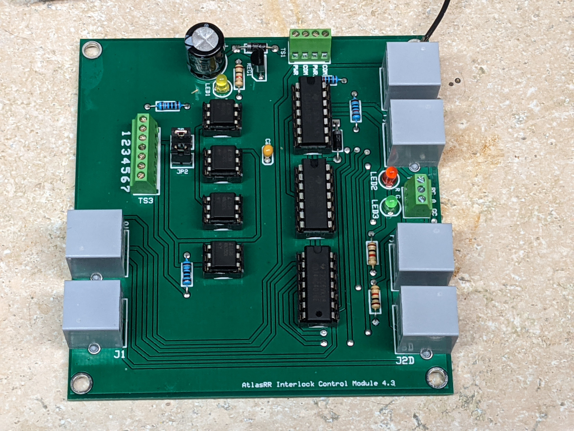
The Interlock Control Module
For siding ends and such, Atlas offers a companion board – the Interlock Control Module. To actually build a siding end, you need one of these ICM boards and 4 USCBs – one for each signal head. Yikes. That’s a lot of interconnecting for an “easy” system, but Atlas details out how to do it on page 13 of the ICM user manual.
The manual for the ICM can be found on Atlas’ website here and shows how to connect the thing to both your switch machine and to the gaggle of USCBs needed to make it work.
Reverse Engineering the Atlas System
The most obvious difference is that MSS is an open, well-defined standard, whereas the Atlas system is a closed ecosystem. Somewhat surprisingly, I couldn’t find anybody that had done any work on understanding how the Atlas signal bus works, so I decided to buy a few boards and do some poking around. My guess, based on just looking at them, was that the scheme would be extremely similar to MSS.
The toughest thing to get my brain around is that the ports on the Atlas boards aren’t symmetric, since they’re intended for unidirectional signaling. Atlas boards have two distinct ports, one for upstream (J2) and one for downstream (J1). J2 connects to the J1 of the previous block in the direction being signaled, and J1 connects to the J2 of the next block.
Atlas puts 6 conductor ports on the boards, but only the inner four are connected so that standard straight-through 4-conductor telephone wire works. The outer pins (1 & 6) are not connected to anything.
The Atlas signal bus is an open collector (aka open drain) system. A low (near ground / 0V) signal means “active”. If a signal is not active, the line will be left to float, pulled up by modules that use its state. In theory this should get it to near 5V, but I’ve seen cases where it’s extremely weakly pulled to supply voltage instead, probably from leakage through contamination on the board. (Several of my boards were sticky, implying that the flux hadn’t been fully cleaned off.) One thing of note is that a common ground isn’t carried on the bus, so it’s incredibly important that all signal modules share a common ground wire on their power connection. Otherwise you’re going to get all sorts of wacky results (at best) or much popping and burning (at worst).
J1 Pinout – Connects to next block in direction of travel
Pin 1 – (no connection)
Pin 2 – OUT: GND=Block controlled by board is occupied
Pin 3 – IN: GND=Next block signal is red/stop
Pin 4 – IN: GND=Force this block’s signal to red
Pin 5 – IN: GND=Next block signal is yellow/approach
Pin 6 – (no connection)
J2 Pinout – Connects to previous block in direction of travel
Pin 1 – (no connection)
Pin 2 – IN: GND=Previous block occupied (used for approach lighting)
Pin 3 – OUT: GND=This block is occupied
Pin 4 – IN: GND=Force this block’s signal to red
Pin 5 – OUT: GND=This block’s entrance signal is yellow/restricting
Pin 6 – (no connection)
Schematics
What would a reverse engineering effort be without actual schematics? That’s how I figured out what each board did and how it did it to start with. If you spot an error, let me know.
USCB v2.5 Schematic PDF (Updated Aug 17, 2021)
ICM v4.3 Schematic PDF (Updated Aug 17, 2021)
For those interested in the original files and seeing if I’ve put up anything new, here’s the Github repository for my efforts.
Interfacing to an Arduino
Honestly this is way easier than with MSS, because you don’t have to deal with all the level shifting and 12V signal levels. You’ll need a common ground with the Atlas system, but after that you can hook the inputs you need straight into the Arduino because they’re 5V. The outputs are a little trickier, because they need to be open collector / open drain. Fortunately you can do this in software:
void digitalOpenDrainWrite(byte pin, bool value){pinMode(pin, (value)?INPUT_PULLUP:OUTPUT);digitalWrite(pin, (value)?HIGH:LOW); }
At that point, it’s as simple as reading the inputs, setting your signal, and writing the outputs. Remember that setting an output LOW means that it’s active / true, and setting it HIGH means that it’s not active / false. So if you want to indicate to the previous block that you’re a red signal, you would set J2 pin 3 low.